BASICS OF BREAD BOARD
A breadboard is used to make up temporary circuits for testing or to try out an idea. No soldering is required so it is easy to change connections and replace components. Parts will not be damaged so they will be available to re-use afterwards.
Almost all the Electronics Club projects started life on a breadboard to check that the circuit worked as intended.
The photograph shows a typical small breadboard which is suitable for beginners building simple circuits with one or two ICs (chips). Larger sizes are available and you may wish to buy one of these to start with.
Connections on Breadboard
Breadboards have many tiny sockets (called 'holes') arranged on a 0.1" grid. The leads of most components can be pushed straight into the holes. ICs are inserted across the central gap with their notch or dot to the left.
Wire links can be made with single-core plastic-coated wire of 0.6mm diameter (the standard size). Stranded wire is not suitable because it will crumple when pushed into a hole and it may damage the board if strands break off.
The diagram shows how the breadboard holes are connected: 
The top and bottom rows are linked horizontally all the way across as shown by the red and black lines on the diagram. The power supply is connected to these rows, + at the top and 0V (zero volts) at the bottom.
I suggest using the upper row of the bottom pair for 0V, then you can use the lower row for the negative supply with circuits requiring a dual supply (e.g. +9V, 0V, -9V).
The other holes are linked vertically in blocks of 5 with no link across the centre as shown by the blue lines on the diagram. Notice how there are separate blocks of connections to each pin of ICs.
Large Breaboards
On larger breadboards there may be a break halfway along the top and bottom power supply rows. It is a good idea to link across the gap before you start to build a circuit, otherwise you may forget and part of your circuit will have no power!
Building a Circuit on Breadboard
Converting a circuit diagram to a breadboard layout is not straightforward because the arrangement of components on breadboard will look quite different from the circuit diagram.
When putting parts on breadboard you must concentrate on their connections, not their positions on the circuit diagram. The IC (chip) is a good starting point so place it in the centre of the breadboard and work round it pin by pin, putting in all the connections and components for each pin in turn.
 |
| Monostable Circuit Diagram |
The best way to explain this is by example, so the process of building this 555 timer circuit on breadboard is listed step-by-step below.
The circuit is a monostable which means it will turn on the LED for about 5 seconds when the 'trigger' button is pressed. The time period is determined by R1 and C1 and you may wish to try changing their values. R1 should be in the range 1k![]() to 1M
to 1M![]() .
.
Time Period, T = 1.1 × R1 × C1
For further information please see 555 monostable.

IC pin numbers
IC pins are numbered anti-clockwise around the IC starting near the notch or dot. The diagram shows the numbering for 8-pin and 14-pin ICs, but the principle is the same for all sizes.
Components without suitable leads
![]() Some components such as switches and variable resistors do not have suitable leads of their own so you must solder some on yourself. Use single-core plastic-coated wire of 0.6mm diameter (the standard size). Stranded wire is not suitable because it will crumple when pushed into a hole and it may damage the board if strands break off.
Some components such as switches and variable resistors do not have suitable leads of their own so you must solder some on yourself. Use single-core plastic-coated wire of 0.6mm diameter (the standard size). Stranded wire is not suitable because it will crumple when pushed into a hole and it may damage the board if strands break off.
Building the example circuit
Begin by carefully insert the 555 IC in the centre of the breadboard with its notch or dot to the left.
Then deal with each pin of the 555:
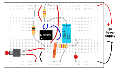 |
| Monostable Circuit on Breadboard |
- Connect a wire (black) to 0V.
- Connect the 10k resistor to +9V.
Connect a push switch to 0V (you will need to solder leads onto the switch) - Connect the 470 resistor to an used block of 5 holes, then...
Connect an LED (any colour) from that block to 0V (short lead to 0V). - Connect a wire (red) to +9V.
- Connect the 0.01µF capacitor to 0V.
You will probably find that its leads are too short to connect directly, so put in a wire link to an unused block of holes and connect to that. - Connect the 100µF capacitor to 0V (+ lead to pin 6).
Connect a wire (blue) to pin 7. - Connect 47k resistor to +9V.
Check: there should be a wire already connected to pin 6. - Connect a wire (red) to +9V.
Finally...
- Check all the connections carefully.
- Check that parts are the correct way round (LED and 100µF capacitor).
- Check that no leads are touching (unless they connect to the same block).
- Connect the breadboard to a 9V supply and press the push switch to test the circuit.
If your circuit does not work disconnect (or switch off) the power supply and very carefully re-check every connection against the circuit diagram.
Rapid Electronics have kindly allowed me to use their images on this page. Rapid stock a wide range of components, tools and materials for electronics. I am happy to recommend them as a supplier for individuals and education. In my experience their standard delivery really is rapid!